FINISHING - Page 89.
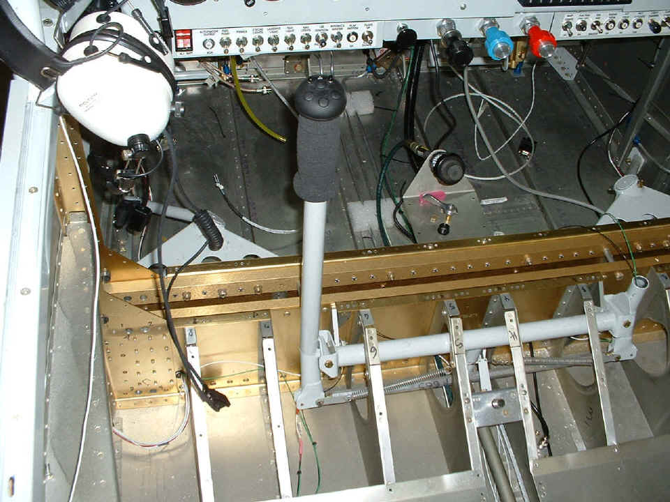
January 26, 2005: Time to wire up the
push-to-talk switches on the joy sticks. Look carefully at the bottom of the pilot's
control stick and you will see a green wire and a black wire disappearing up into the
bottom of the stick. The green wire comes from the communications radio. The
black wire goes to a nearby ground lug at the top of seat rib number SIX, although from
this perspective the SIX is upside down and looks like a NINE but is next to number FIVE,
so that gives it away. I also soldered and crimped a second black ground wire in
that lug and ran it across to the other stick which is still vacant in this photo. I
went out to Radio Shack since they are open until 9 PM to get a pair of inline phone
plugs, male and female to keep the stick on the right side removable, but still able to
have a push-to-talk button functioning when the stick is installed. After I got the
PTT switches wired, I checked out the COM radio on 122.75 MHz (air-to-air) to be sure the
transmitter really works, and from both seats.
I only hooked up the PTT button on the LEFT stick for now, since I don't have
electric trim on this airplane. Those extra buttons are eventually going to be used
on a video camera system someday. So much for my electrical and soldering skills, I
might as well cut out paper dolls! Well, maybe I should cut out paper templates for
the firewall insulation. That Wachovia letter opener is on my desk as I
update these web pages with larger photos on Thanksgiving
Day November 24, 2022 here in Kissimmee, Florida.
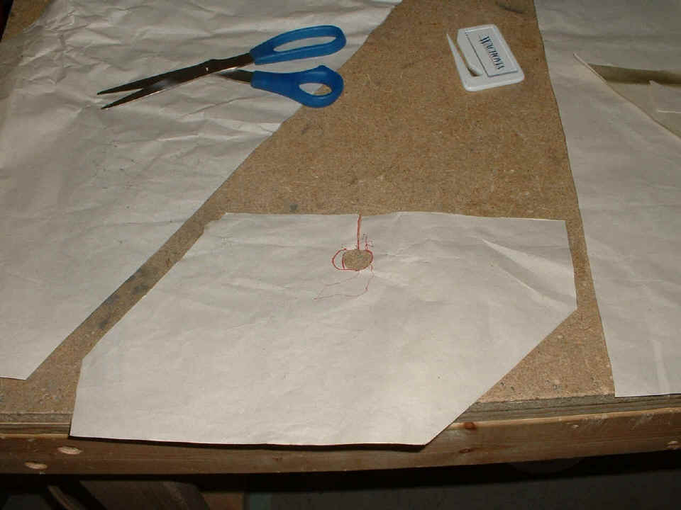
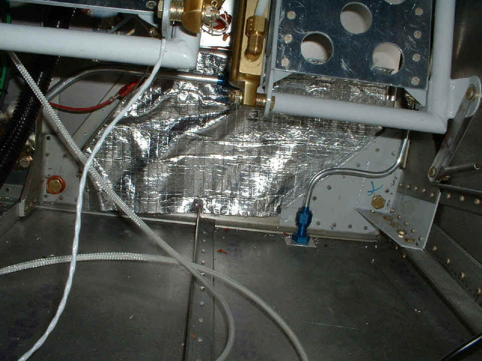
After fitting the template above, I cut out this section of insulating blanket
and placed it behind the fuel line and on the section of wall that mounts the gascolator
on the engine side of the firewall. Some of the blanket is in between the gray steel
weldment and the firewall at the bottom right corner, just in front of the fuel vent line
(blue AN fitting) on the floor. I will need some of that spray-on Sticky Stuff to be
sure this thing stays in place on the RIGHT side, but the LEFT top side is firmly wedged
in behind the right-angle AN fuel line fitting that connects to the gascolator. That
blue AN fitting is mostly hidden behind the master cylinder on the right rudder pedal.
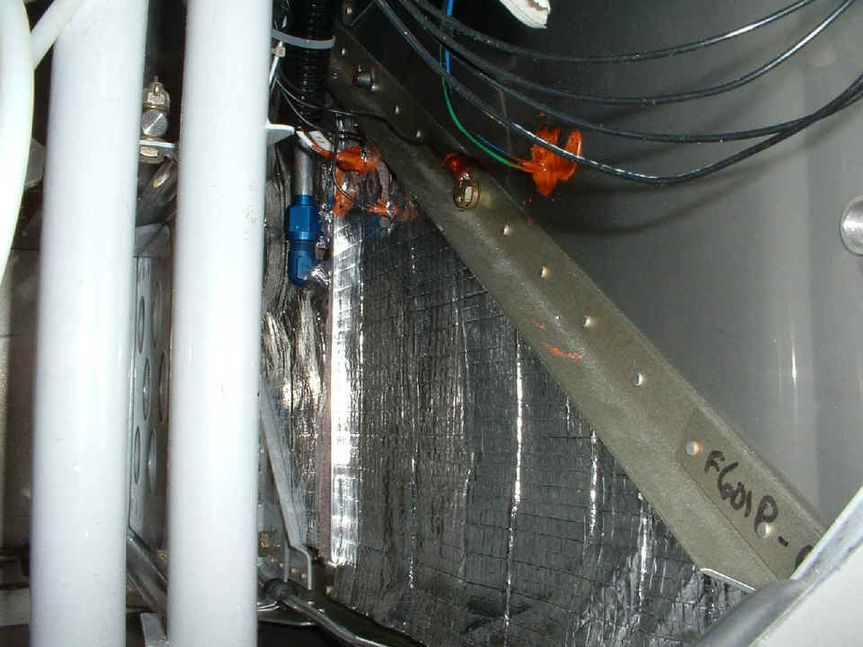
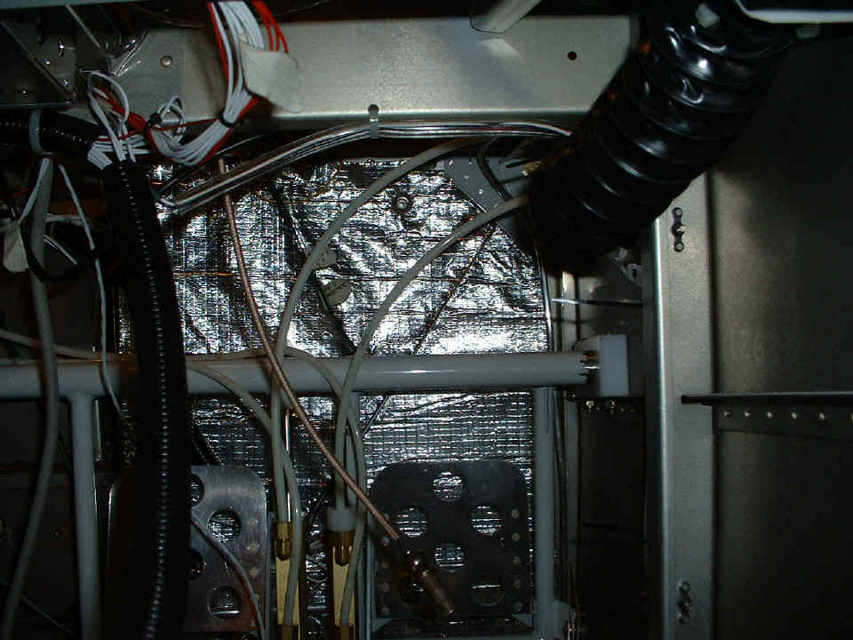
The last picture of the night (looking down) shows a second triangular panel
mounted above the first one above the gascolator doubler. There are two holes cut in
this one and slits to the holes to allow wires to pass through the insulation. This
picture is looking down on the right-angle AN fitting to the gascolator. The rudder
bars are the two gray round bars at the left side of the photo. Next session will
find me making the triangle to fit above those two earlier panels. The main
electrical wires go through this section of firewall, along with some sensor wires you can
see at the RED RTV glob in the picture. There is also a fluid connection to the
brake fluid reservoir at the extreme right edge of the photo. You will see that
reconnected after I put the next blanket in place. All those other black wires are
ground wires going to a bolt near the manifold pressure port through the firewall, which
is just out of this picture near the upper right corner.
Another 4.8 hours gets added to the log book on tonight's session and a minor milestone or two to give that feeling of accomplishment! That brings the total construction time to 1598.0 hours. It is starting to look like 1700 to 1800 hours for the project to reach the first flight.
January 27, 2005: 1600+ hours of the project
are now behind me in this project and there is only one picture worth taking tonight.
Wiring ain't sexy, but the thermal blanket got another section added and that at
least is something that shows - and here it is. Look carefully and you will see a
very straight line running from the top right of the fuselage diagonally down behind the
rudder pedals. That is the edge of a 3/4"x3/4" angle that stiffens the
firewall. That round fitting peeking through the blanket near the top is access to
the brake fluid reservoir.
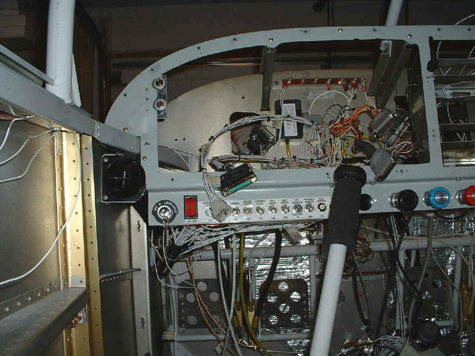
Oh yes, the panel is empty again. I needed the room
to clean up the wiring I mentioned. I realized the only thing on the ESS bus was the
radar transponder and one inside light circuit. When I checked out the total current
draw of the avionics, I put in one more wire to the circuit breaker for the radar
transponder to add it to the 20-ampere avionics circuit breaker. I also finished the
wiring from the NavAid controller to the LEFT wing wiring port and added a Molex connector
to the end of those three wires. When I removed the RIGHT panel with the stereo in
it, I realized that the connection of the speaker wires to the power plug on the stereo
now required me to put a second three-pin Molex connector in series with the power wires
to the stereo unit itself. That was the only way I could get the panel out cleanly.
That makes three plugs to disconnect when removing the RIGHT panel from the rest of
the wiring harnesses, plus the two phono audio plugs.
I also made some additional connections to the NAV/COM radio. The CDI left/right outputs have also been connected to the DPDT switch on the main panel allowing me to select VOR/Localizer guidance or GPS guidance for the wing leveler. Since I disconnected the ESS bus, I turned the GREEN LED on the main panel into a transmit light for the COM radio. Of course that means I have to print new labels for the lights, and a new label for the RIGHT switch/breaker sub-panel.
The main panel has a number of plugs to disconnect when getting it out of the panel frame. Here is the list of items that have to be disconnected when the LEFT main panel is removed:
1. One 12-pin Molex power plug to the Navaid Devices wing leveler
controller.
2. One 12-pin Molex power plug to all warning lights and the VOR CDI/GPS left/right
signals for the wing leveler.
3. One 25-pin D-sub power plug to the Dynon display unit.
4. Two 25-pin D-sub plugs on the back of the GRT EIS engine monitor.
5. One round multi-pin connector for the EI dual fuel gauge.
6. One RJ-45 telephone connector to the ELT control panel.
7. GPS 196 data/power cable and BNC antenna connector.
8. Two air lines for the pitot tube and static air.
9. Two air lines for the LIFT RESERVE INDICATOR stall warning device. Those
lines will not be installed until I get
to the airport and put the wings on the airplane.
January 28, 2005: I just realized I had
entered the date incorrectly above, and have now fixed that with this entry. I
usually have short sessions on Fridays and that is the case again this evening. One
panel of insulation has been fitted to the LEFT side of the firewall.
A bolt that holds the oil pressure monitoring line to the firewall has been
turned around to allow the easy connection of the assembly that supports the LSE ignition
control module and the altitude encoder. I just realized how much I had scuffed the
firewall drilling that hole, using the pop-rivet tool, then drilling out the rivet when it
was time to take that angle and panel assembly out to insulate the firewall. The
lower half of the bolt head is visible in the shadow of the angle that goes across the
firewall. That angle on the right that has one hard rivet holding it to the angle on
the firewall is the same one that goes up to brace the windshield center bar. The
RED RTV is sealing the center recessed firewall panel behind the engine.

Today's installed thermal blanket segment fills the lower left quadrant of this
photo. That is just a small portion of the triangular insulating panel.
I will be away for at least a week, so be patient, I will be back soon and resume speed on the project. The weather here in the south is nasty, but I have an ice-free route that will get me from Chattanooga down past that freezy skid stuff that is covering Atlanta. (Can you say Birmingham, Alabama?) I have to go south, and it needs to be now, so see you all later online.
February 6, 2005: I
got back home late on Saturday night, February 5th, and went out to Dallas
Bay Skypark (1A0) on Sunday (6th)
to see a hangar that is available but it was locked and they could not find the key.
Oh, well. I had received a call when I was in Florida and hoped to see the
hangar. As it stands, there is one other person on the list for hangar space who may
have a more pressing need than mine, but since they are building new hangars soon, it may
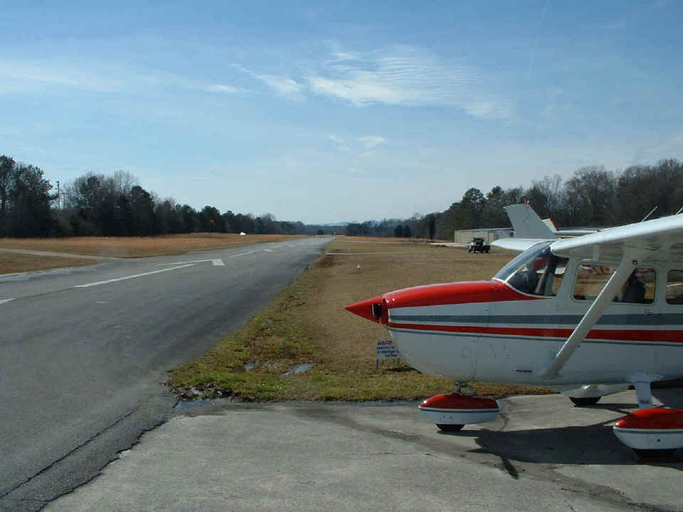
not be an issue for me. I took this one picture of the 3000-foot long runway with
its displaced threshold on the north end.
I logged onto the Aircraft Spruce & Specialty web site after a conversation with David Edgemon about parking brake valves and the parts that go with it. All those parts are now on order and should be here on Tuesday. I do have a few pictures of some new work on the project, but since this page now has eight pictures, let's move on to page 90 for the early details of the filtered air box.
| CLICK HERE for Finishing Page 90. | RETURN to MAIN MENU. |