Wendell Folks RV-8 Project - Page 30.
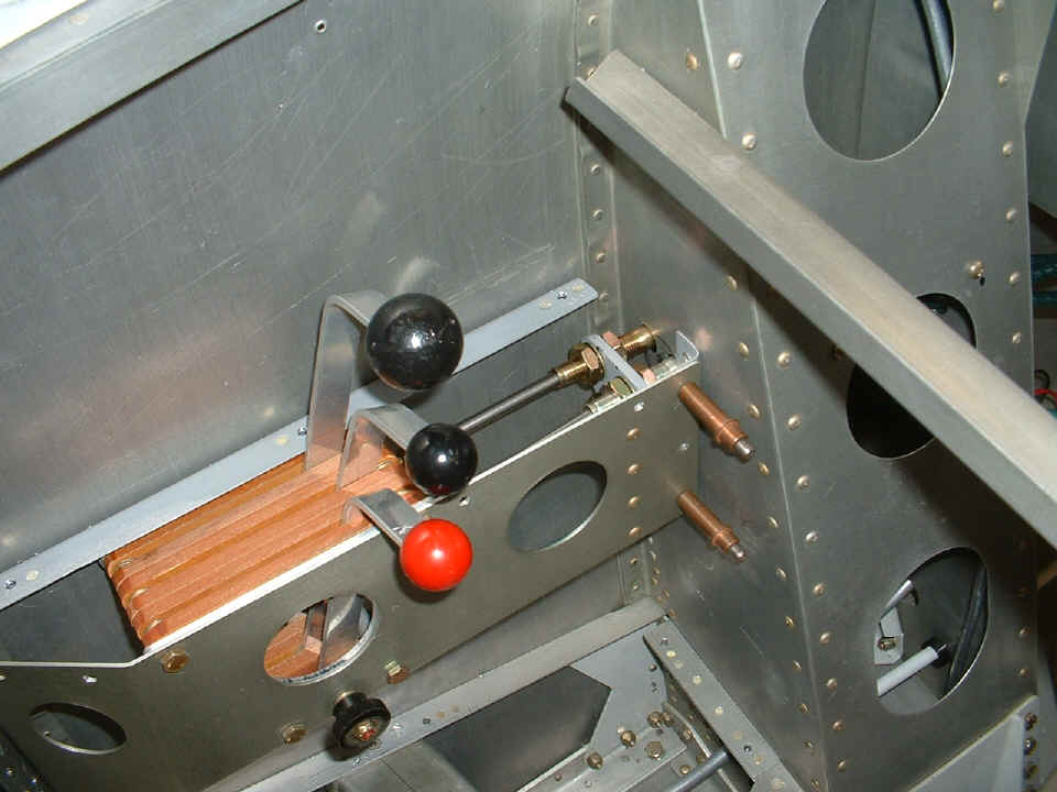
October 7, 2006: The engine controls had to
be installed again temporarily to insure the proper clearance of the control cables
through the left main gear leg tower. We discovered that two of the holes needed
some additional work to clear the control cables.
The first of the rubber "O-rings" to stabilize the control cables is
installed. The next step is to insert one of the control cables, then fit up the
stainless steel shields that will be installed over the rubber parts.
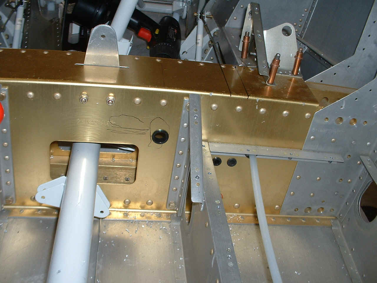
Back in the cabin, the plastic bushings were installed for wiring and the two
air lines from the LIFT RESERVE PROBE that will be mounted underneath the right wing
access panel to the aileron bellcrank. We had the foot wells laid into the floor to
be sure the air lines would not have an interference fit problem as they come in from the
wing, loop around near the floor support rib, then penetrate the wing spar box. The
two 1/4" plastic bushings will pass the air lines for the LRI gauge on the instrument
panel. The large plastic bushing near the control stick assembly will pass a number
of wires going from the switch/breaker panel to wing lights, strobe power supply, master
relay, etc.
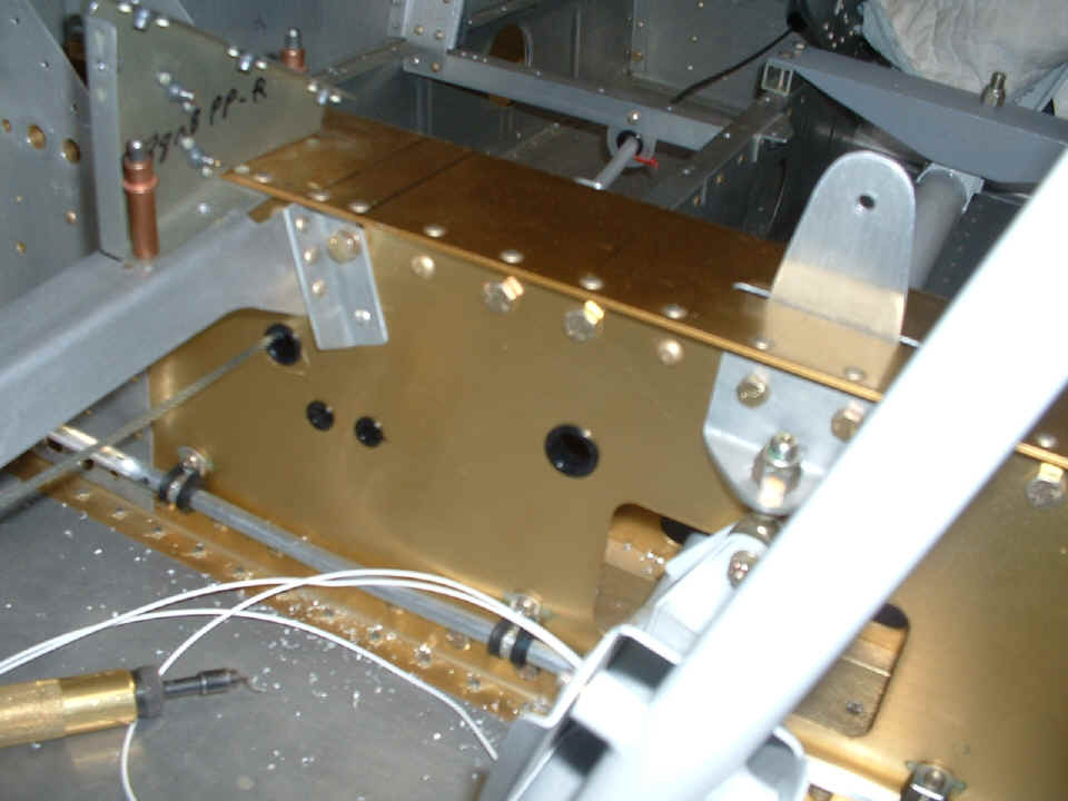
Here are the matching bushings installed on the front of the wing spar
assembly. After uploading this photo to my computer, I realized I should have turned
on the "macro mode" in my camera to take this shot.
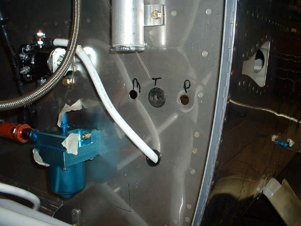
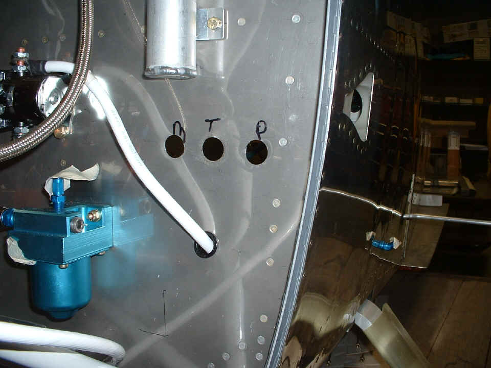
The last shot of the day shows all three engine control cable access holes
drilled to full size. These holes are now at 3/4" diameter to accept 1-inch
rubber "O-rings". The gascolator now has a steel plug in the fuel line
access hole on this side. The fuel primer solenoid will be mounted nearby after all
the control cables have their stainless steel shields installed.
October 12, 2006: The
session with Wendell tonight checked his recent work and charted his next building steps.
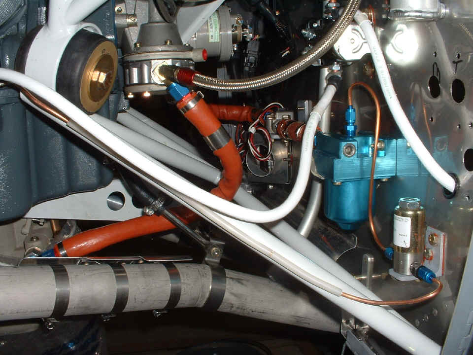
There is a lot to see in the photo below. Let's start at the far right side
of the photo. The clearance holes for the control cables have now been fitted with
stainless steel fire shields and the large rubber grommets have been removed. The
screw holes for the shields are now visible above and below the larger holes in the
firewall. The next thing new is the solenoid for the primer system and the copper
lines from the gascolator to the valve and continuing to the first tee in the primer lines
on the engine. The copper tubing is "armored" by some left over brake
tubing from my surplus materials. There is an expansion loop in the primer line as
it approaches the engine mount. That half loop bends toward the camera is not very
apparent. The starter cable has been shaped to fit along the route from the crank
case going to the starter solenoid on the firewall. Two clamps will hold it to the
engine mount when completed. There are now three heat shields on the exhaust pipe
near the fuel line going to the carburetor.
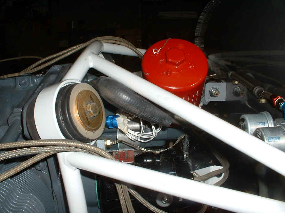
Behind the gascolator in the photo above, you can see the first view of the
crankcase vent pipe up against the firewall. This is the initial fit of the pipe and
its mating rubber hose up on the engine accessory case as seen in the photo below.
The hose has been trimmed to a length that provides needed clearance from the oil filter
and the oil cooler hose that will come from the blue AN-fitting near the center of the
photo. The spark plug wires are just draped where needed to stay out of the way of
the other work going on. Those coiled white wires near the center are from the oil
temperature probe, which will be connected when the engine monitor is installed.
Here is a view of the number two cylinder and primer lines there. The
original primer lines that came with the engine are installed along with the brass tee
fittings. Ansel clamps have been installed on the intake pipes to prevent
oscillations of the primer lines between the tee and the cylinder heads where the brass AN
spray nozzles are installed. The front end of the large starter cable is also
visible. There will be one Ansel clamp installed to secure that cable to the flange
above the oil sump.
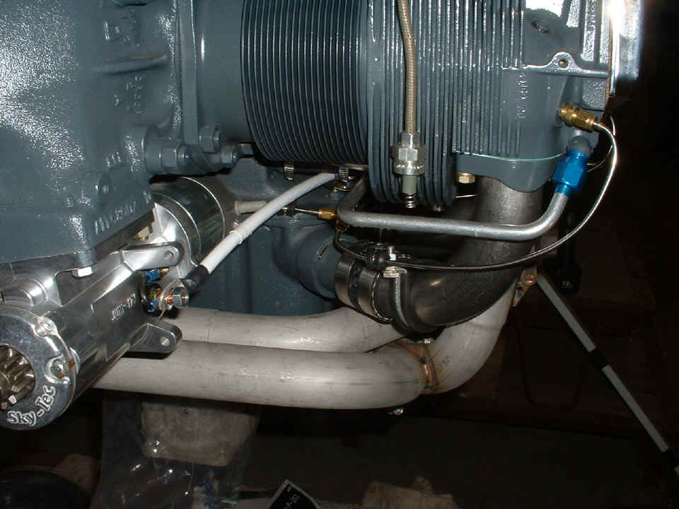
The view from the right side of the engine shows the control cables from the
Lasar ignition system. Wendell has placed a clamp on the cables where he was
checking the attach point to the firewall I recommended. The "breather
tube" from the crank case is also visible. It will get a second clamp installed
down below the fuel line coming from the gascolator to the fuel flow sensor. The
lower end of the tube will also get trimmed to insure proper clearance above the left
exhaust pipe where any dripping oil should be vaporized when it hits the hot pipe.
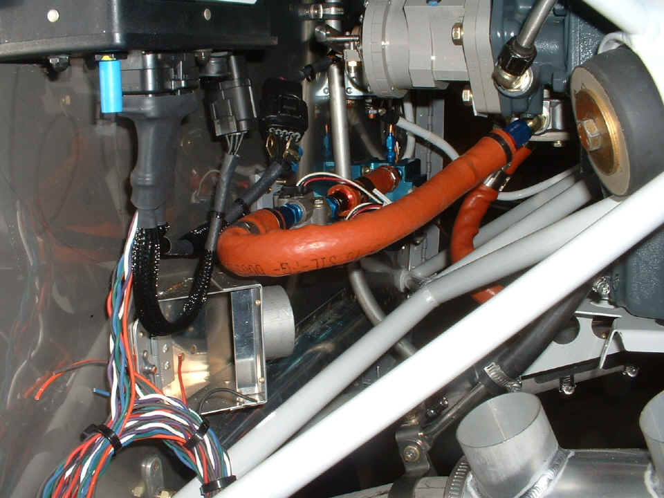
Now that things are getting full on this side of the engine, it was also time to
insure that a grounding point on the firewall was selected for another large cable to give
a return electrical path for the starter motor. The ground cable bolts to the crank
case near the oil dip stick and the engine mount seen in the top right corner of this
photo. All those colored wires from the Lasar ignition control module will soon find
an entry point through the firewall.
| CLICK for Folks PAGE 31 | Return to Other RV Menu | Return to Main Menu Page. |